Wednesday, April 12, 2017

FLUORESCENT LIGHT WIRING DIAGRAM

This post "Fluorescent Light Wiring Diagram | Tube Light Circuit" is about how to wiring fluorescent light and "how a Fluorescent Tube Light works". The wiring process of fluorescent tube lamp/light with Ballast,Starter is quite easy and simple. In most cases when we buy a fluorescent light it comes in a complete set with all wire connected. If you want do it yourself (DIY), you can buy all the parts individually. And you can complete all connection of the fluorescent light/lamp with the help of this wiring circuit diagram.


Fluorescent Light Wiring Diagram


Fluorescent Light Wiring Diagram-Tube Light Circuit

Main parts of Fluorescent Tube Light:

     1.Fluorescent Tube
     2.Ballast
     3.Starter
     4.Holder, wire etc


How Fluorescent Light's works:

The starter is like a key of fluorescent light because it is used to light up the tube. When we connect the AC supply voltage to the circuit, then the starter act like short circuited and current flow through those filament (located at the first and second end of the tube light) and the filament generate heat and it ionized the gas (mercury vapor) in the fluorescent tube lamp. So the gas becomes electrically conductive medium. At the same time when the starter opened the circuit path of two filaments from series connected, then the ballast release its stored voltage. And it makes the fluorescent tube fully lighten. Now the starter has no job in the circuit, if you open it from the circuit the fluorescent tube light will be still lighten, until you release the main supply.


SIMPLE WIRING DIAGRAM OF CEILING FAN


ceiling fan wiring diagram
Fig-1:  Ceiling fan wiring diagram

This is a simple illustrated circuit diagram of ceiling fan. To be noted that the wiring diagram is for AC 220V single phase line with single phase ceiling fan motor. Here a simple SPST switch is used to supply power or not to the fan motor and a Regulator is used to controlling the fan speed. Though it is very simple, but one thing to be noted that Switch and Regulator should be connected with the phase line of main power, not neutral.


Capacitor connection diagram of ceiling fan

Ceiling fan has a “capacitor start motor” in its inside. AC single phase capacitor start motor has two winding; one is starting winding and another is running winding.

ceiling fan capacitor wiring diagram
Fig-2:  Ceiling fan capacitor connection diagram

As it is a capacitor start-capacitor run type motor; there a capacitor is used in series with Starting Winding, It defines the direction of rotation. It is an electrolytic capacitor.

Sometimes you may have faced this type of question...

  1. Why ceiling fan rotating in reverse?
  2. What makes a ceiling fan run backwards?
Two of this question sounds the same; the answer of the both question is “If capacitor is connected with running winding/main coil instead of starting winding/auxiliary coil then the direction of rotation will changed. That’s mean if you want to change the direction of rotation of the fan, just connect the capacitor with other winding.

Tuesday, January 31, 2017

Top 11 Things You Didn't Know About Nikola Tesla TOP 11 THINGS YOU DIDIN'T KNOW ABOUT NIKOLA TESLA

Image result for nikola tesla inventions


11. Tesla was born on July 10, 1856, in the Austrian Empire, now Croatia. He was the fourth of five children. After a checkered academic career in Europe, he worked as a telegraph drafter and electrician before moving to the United States to work for Thomas Edison in 1884.
10. If you couldn’t imagine life without your TV remote, thank Nikola Tesla for making it possible. Tesla invented, predicted or contributed to development of hundreds of technologies that play big parts in our daily lives -- like the remote control, neon and fluorescent lights, wireless transmission, computers, smartphones, laser beams, x-rays, robotics and, of course, alternating current, the basis of our present-day electrical system.
9. Innovation runs in Tesla’s blood. Tesla once wrote: “My mother was an inventor of the first order and would, I believe, have achieved great things had she not been so remote from modern life and its multi fold opportunities. She invented and constructed all kinds of tools and devices and wove the finest designs from thread which was spun by her.” He credited both his parents’ influence for his success.
8. Tesla lived in New York City for 60 years, and remnants of his time there still remain. The corner of 40th Street and 6th Avenue in downtown Manhattan has been designated “Nikola Tesla Corner” -- with its own street sign -- because of its proximity to Tesla’s laboratory at 8 West 40th Street, where he worked in 1900 while building his now-infamous Tesla Tower on Long Island. At nearby Bryant Park Place, a plaque commemorates the Engineer’s Club, which awarded Tesla the Edison Medal on May 18, 1917. During his later years, Tesla fed pigeons in nearby Bryant Park.
7. Tesla received his U.S. citizenship in 1891, the same year he invented the Tesla coil. Tesla coils are a type of electrical circuit used to generate low-current, high-voltage electricity. Today, they’re widely used in radios, televisions and other electronics, and can be used for wireless transmission. A coil at Tesla’s experimental station in Colorado Springs, Colorado, created 30-foot sparks that could be seen from 10 miles away.
6. During the war of the currents, alternating current (AC) -- favored by Tesla -- battled for wide acceptance with direct current (DC), favored by Edison. At stake was the basis for the entire nation’s electrical system. Edison launched a campaign against AC, claiming it was dangerous and could kill people; Tesla countered by publicly subjecting himself to 250,000-volt shocks to demonstrate AC’s safety. Ultimately, alternating current won the fight.
5. Tesla designed the first hydroelectric power plant in Niagara Falls, New York, harnessing the power of the waterfalls he had marveled at since childhood. Construction took three years and power first flowed to homes in nearby Buffalo on Nov. 16, 1896. A statue of Tesla on Goat Island overlooks the falls today.
4. “Teslas,” a unit used to measure the strength of magnetic fields, are named after Tesla. Another namesake is Tesla Motors, the electric car start-up, in homage to Tesla’s role in the invention of the electric motor.
3. In 1901, Tesla received financial backing from J. Pierpont Morgan to build his Wardenclyffe laboratory in Shoreham, Long Island. The facility included the “Tesla Tower,” a 185-foot high structure with a 65-foot copper dome transmitter on the top. Tesla’s vision was to use the tower to transmit signals and free, unlimited wireless electricity all over the world. Thanks to Tesla's early work, wireless transfer of energy is finally being realized today -- from wireless chargers for electric toothbrushes and smartphones, to wireless electric vehicle charging, a technology being researched at the Energy Department’s National Labs.
2. Tesla was not a savvy businessman and suffered financially, despite his achievements. He lost financial backing from Morgan, who felt he couldn’t profit from Tesla’s wireless electricity concept, and sold his assets to make up for dual foreclosures on Wardenclyffe. The property was later sold to a film processing company. In 1917, the U.S. government demolished Tesla’s partially completed tower because it worried German spies would use it to intercept communications during World War I.
1. His long-abandoned Long Island laboratory will soon become a museum. Earlier this year, a non-profit organization raised enough money to purchase the long-abandoned Wardenclyffe. The group plans to restore the building and turn it into a Tesla museum and science education center.  

INTERESTING FACTS ABOUT ELECTRICITY

                      Image result for ELECTRICAL INTERESTING THINGS


Interesting facts about electricity

Here are some interesting (and somewhat weird) electricity facts:
  1. All though it is commonly thought that Thomas Edison invented electricity, it was in fact Benjamin Franklin who discovered that lighting and electricity is pretty close to being the exact same thing, but he didn’t invent energy, as energy cannot be destroyed or created, just transformed. Thomas Edison built the very first power plant in 1882 in New York and that year it supplied 85 buildings with electricity. This plant, Pearl Street Station in lower Manhattan, started with one generator and it produced power for 800 electric light bulbs. Within 14 months, the Station had 508 electricity consumers and over 12 000 bulbs. Since 1882, the electricity industry has grown to generate over 2.5 million watts-hours yearly, which equates to the lighting of 4.8 billion 60 watt incandescent light bulbs annually. He was also responsible for the first light bulb to stay lit for more than a few seconds, along with inventing more than 2000 new products like fuses, switches, meters and sockets and helped with the invention of DC (Direct Current).
  2. Fireflies produce light using chemical energy from their food. This light is even more efficient than that of one light bulb. Other creatures possess this magic too, like the deep sea squid and glow worms. An electric eel on the other hand, does not glow, but it can provide a shock of 600 volts, that is double the 220 volts which can be safely plugged into a socket in your home.
  3. One bolt of lightning has enough electricity to supply 200 000 average size homes!
  4. Iceland is the first and only country to date which relies solely on renewable sources for electricity.
  5. Ever wondered why a bird does not get electrocuted sitting on a power line? That is because both feet are on one power line. As soon as a part of its wing or one foot, touches another power line, a circuit would be created flowing through the body of the bird, causing electrocution.
  6. Sufficient amounts of sunlight reach the earth every minute to satisfy the entire worlds’ energy demands for a year.
  7. I think it is safe to assume almost all of us have used Google numerous times. They account for about 0.013% of the worlds’ energy usage. This equals enough electricity to power 200 000 homes continuously. The energy it takes to conduct 100 searches on their website, is the equivalent of a light bulb burning for 28 minutes.
  8. A refrigerator uses less energy than a Playstation 3.
  9. The average laptop idles at 20 watts, while a desktop computer idles at 80 watts.
  10. The Statue of Liberty was the first lighthouse to use electricity in 1886.
  11. The first bridge that used electricity was the Brooklyn Bridge in New York.
  12. Electricity can be made from wind, light, water and even animal manure.
  13. It is a little known fact that only ten percent of the traditional light bulb is used for actual lighting. The other 90% of the energy creates heat.
  14. During a hurricane, 50 to 200 trillion watts of heat energy are released. This is the same amount of energy as a 10 megaton nuclear bomb exploding every 20 minutes.
  15. A simple spark of electricity, can measure up to 3000 volts.
  16. South Africa was the country with the cheapest electricity in the developed world. That was until the staggering 27.8% tariff increase. According to the Electricity Report & Pricing Survey, Canada is now the cheapest in the world, with South Africa following in second place with a 7% higher electricity tariff than Canada. Italy and German on the other hand, has the most expensive electricity rates in the world.
  17. The speed of electricity is considered faster than any other thing in the world at 300 000 km per second. In fact, if you had a light switch in your house connected to a bulb on the moon, you could go around the world 8 times during the time it takes you to light the bulb by just turning on the switch.
  18. Eskom is responsible for approximately 95% of all electricity used in South Africa and about 45% of Africa’s usage.
  19. The difference between AC (Alternating Current) and DC is in the way the electrons flow. With DC electrons move in a single direction, while in AC, electrons constantly switch direction. AC is what we use in most homes, as it is much safer and it used over longer distances than DC can.
  20. Alessandro Volta was the one who discovered that when two strips of different metals were placed in sulfuric acid and connected to a simple wire, electricity flowed. Thus, he invented the first electric battery.

GROUNDING


                                     Image result for electrical grounding


Electrical grounding or “Grounding” originally began as a safety measure used to help prevent people from accidentally coming in contact with electrical hazards. Think of your refrigerator. It is a metal box standing on rubber feet with electricity running in and out of it. You use magnets to hang your child’s latest drawing on the metal exterior. The electricity running from the outlet and through the power cord to the electrical components inside the refrigerator are electrically isolated from the metal exterior or chassis of the refrigerator.


                                             Image result for electrical grounding


If for some reason the electricity came in contact with the chassis, the rubber feet would prevent the electricity from going anywhere and it would sit waiting for someone to walk up and touch the refrigerator. Once someone touched the refrigerator the electricity would flow from the chassis of the refrigerator and through the unlucky person possibly causing injury.
Grounding is used to protect that person. By connecting a green ground wire from the metal frame of the refrigerator, if the chassis inadvertently becomes charged for any reason, the unwanted electricity will travel through the wire back to your electrical panel, and tripping the circuit-breaker stopping the flow of electricity. Additionally, that wire must be connected to something that is in turn connected to the earth or ground outside. Typically this connection is a grounding electrode, such as a ground rod.
The process of electrically connecting to the earth itself is often called “earthing”, particularly in Europe where the term “grounding” is used to describe the above-ground wiring. The term “Grounding” is used in America to discuss both below-grade earthing and above-grade grounding.
While electrical grounding may have originally been considered only as a safety measure, with today’s advances in electronics and technology, electrical grounding has become an essential part of everyday electricity. Computers, televisions, microwave ovens, fluorescent lights and many other electrical devices, generate lots of “electrical noise” that can damage equipment and cause it to work less efficiently. Proper grounding can not only remove this unwanted “noise”, but can even make surge protection devices work better.


EARTHING IN HEALTH


                          Image result for grounding barefoot


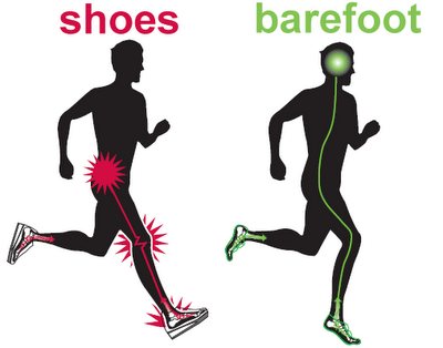
Years of extensive research has shown that connecting to the Earth’s natural energy, by walking barefoot on grass, sand, dirt or rock can diminish chronic pain, fatigue and other ailments that plague so many people today. This connection is referred to as Earthing or Grounding.


To put it briefly, when your bare feet or skin comes in contact with the earth, free electrons are taken up into the body. These electrons could be referred to as nature’s biggest antioxidants and help neutralise damaging excess free radicals that can lead to inflammation and disease in the body. The Earth is a conductor or free electrons and so are all living things on the planet, including us. The body is composed of mostly of water and minerals which in combination are excellent conductors of electrons from the Earth providing there is direct skin contact or some other conductive channel for them to flow through.

The Earth’s energy upgrades one’s physiology by allowing the body to cope and repair thereby promoting wellbeing, vitality and better sleep. It also harmonizes and stabilizes the body’s basic biological rhythms, knocks down (and even knocks out) chronic inflammation and reduces and eliminates associated pain, making it the most natural and powerful anti-inflammatory and anti-aging remedy around! No matter what your age, gender, race or health status you will benefit from a daily dose of Earthing!

EARTH LEAKAGE


                                          Image result for earth leakage


Earth leakage refers to the unwanted flow of electrical current from the live wire (red wire) to the earth wire (green or yellow wire). It is also referred to in some countries as ground leakage or leakage current.

Earth leakage in uncontrolled amounts can be potentially dangerous. It can lead to a rise in voltage, damaging the conducting parts. To detect and control ground leakage, technicians rely on a device known as an earth leakage circuit breaker (ELCB). If a leak is detected, the ELCB automatically cuts of the power supply to the appliance. There are two major kinds of ELCBS: current earth leakage circuit breakers and voltage earth leakage circuit breakers.

Friday, January 27, 2017

POWER FACTOR


Image result for p0wer factor


In electrical engineering, the power factor of an AC electrical power system is defined as the ratio of the real power flowing to the load to the apparent power in the circuit and is a dimensionless number in the closed interval of −1 to 1.

A power factor of less than one means that the voltage and current waveforms are not in phase, reducing the instantaneous product of the two waveforms (V × I). Real power is the capacity of the circuit for performing work in a particular time. Apparent power is the product of the current and voltage of the circuit. Due to energy stored in the load and returned to the source, or due to a non-linear load that distorts the wave shape of the current drawn from the source, the apparent power will be greater than the real power. A negative power factor occurs when the device (which is normally the load) generates power, which then flows back towards the source, which is normally considered the generator.

In an electric power system, a load with a low power factor draws more current than a load with a high power factor for the same amount of useful power transferred. The higher currents increase the energy lost in the distribution system, and require larger wires and other equipment. Because of the costs of larger equipment and wasted energy, electrical utilities will usually charge a higher cost to industrial or commercial customers where there is a low power factor.

Linear loads with low power factor (such as induction motors) can be corrected with a passive network of capacitors or inductors. Non-linear loads, such as rectifiers, distort the current drawn from the system. In such cases, active or passive power factor correction may be used to counteract the distortion and raise the power factor. The devices for correction of the power factor may be at a central substation, spread out over a distribution system, or built into power-consuming equipment.


Definition and calculation


AC power flow has two components:


Real power or active power ({\displaystyle P}), expressed in watts (W)
Reactive power ({\displaystyle Q}), usually expressed in reactive volt-amperes (var).
These are combined to the Complex power ({\displaystyle S}) expressed volt-amperes (VA). The magnitude of the Complex power is the Apparent power ({\displaystyle |S|}), also expressed volt-amperes (VA).

The VA and var are non-SI units mathematically identical to the Watt, but are used in engineering practice instead of the Watt in order to state what quantity is being expressed. The SI explicitly disallows using units for this purpose or as the only source of information about a physical quantity as used

The power factor is defined as the ratio of real power to apparent power. As power is transferred along a transmission line, it does not consist purely of real power that can do work once transferred to the load, but rather consists of a combination of real and reactive power, called apparent power. The power factor describes the amount of real power transmitted along a transmission line relative to the total apparent power flowing in the line.The Power Triangle:


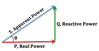
We can relate the various components of AC power by using the power triangle. Real power extends horizontally in the î direction as it represents a purely real component of AC power. Reactive power extends in the direction of ĵ as it represents a purely imaginary component of AC power. Complex power (and its magnitude, Apparent power) represents a combination of both real and reactive power, and therefore can be calculated by using the vector sum of these two components. We can conclude that the mathematical relationship between these components is:
{\displaystyle {\begin{aligned}S&=P+jQ\\|S|^{2}&=P^{2}+Q^{2}\\[3pt]|S|&={\sqrt {P^{2}+Q^{2}}}\\\cos \theta {\text{, power factor}}&={\frac {P{\text{, real power}}}{|S|{\text{, apparent power}}}}\end{aligned}}}


Increasing the Power Factor:

Increased power factor.jpg

As the power factor (i.e. cos θ) increases, the ratio of real power to apparent power (which = cos θ), increases and approaches unity (1), while the angle θ decreases and the reactive power decreases. [As cos θ → 1, its maximum possible value, θ → 0 and so Q → 0, as the load becomes less reactive and more purely resistive].

Decreasing the Power Factor:

Decreased power factor.jpg


As the power factor decreases, the ratio of real power to apparent power also decreases, as the angle θ increases and reactive power increases.


Lagging and Leading Power Factors:
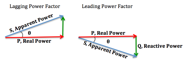
In addition, there is also a difference between a lagging and leading power factor. The terms refer to whether the phase of the current is leading or lagging the phase of the voltage. A lagging power factor signifies that the load is inductive, as the load will “consume” reactive power, and therefore the reactive component  is positive as reactive power travels through the circuit and is “consumed” by the inductive load. A leading power factor signifies that the load is capacitive, as the load “supplies” reactive power, and therefore the reactive component  is negative as reactive power is being supplied to the circuit.
                           Lagging-Leading.jpg

If θ is the phase angle between the current and voltage, then the power factor is equal to the cosine of the angle, :
Since the units are consistent, the power factor is by definition a dimensionless number between −1 and 1. When power factor is equal to 0, the energy flow is entirely reactive and stored energy in the load returns to the source on each cycle. When the power factor is 1, all the energy supplied by the source is consumed by the load. Power factors are usually stated as "leading" or "lagging" to show the sign of the phase angle. Capacitive loads are leading (current leads voltage), and inductive loads are lagging (current lags voltage).
If a purely resistive load is connected to a power supply, current and voltage will change polarity in step, the power factor will be unity (1), and the electrical energy flows in a single direction across the network in each cycle. Inductive loads such as transformers and motors (any type of wound coil) consume reactive power with current waveform lagging the voltage. Capacitive loads such as capacitor banks or buried cable generate reactive power with current phase leading the voltage. Both types of loads will absorb energy during part of the AC cycle, which is stored in the device's magnetic or electric field, only to return this energy back to the source during the rest of the cycle.
For example, to get 1 kW of real power, if the power factor is unity, 1 kVA of apparent power needs to be transferred (1 kW ÷ 1 = 1 kVA). At low values of power factor, more apparent power needs to be transferred to get the same real power. To get 1 kW of real power at 0.2 power factor, 5 kVA of apparent power needs to be transferred (1 kW ÷ 0.2 = 5 kVA). This apparent power must be produced and transmitted to the load in the conventional fashion, and is subject to the usual distributed losses in the production and transmission processes.
Electrical loads consuming alternating current power consume both real power and reactive power. The vector sum of real and reactive power is the apparent power. The presence of reactive power causes the real power to be less than the apparent power, and so, the electric load has a power factor of less than 1.
A negative power factor (0 to -1) can result from returning power to the source, such as in the case of a building fitted with solar panels when their power is not being fully utilised within the building and the surplus is fed back into the supply.

Power factor correction of linear loads

A high power factor is generally desirable in a power delivery system to reduce losses and improve voltage regulation at the load. It is often desirable to adjust the power factor of a system to near 1.0, such that only real power is generated or consumed. When reactive elements near the load supply or absorb that load’s reactive power demand, the apparent power demand on the generator is reduced. Power factor correction may be applied by an electric power transmission utility to improve the stability and efficiency of the network. Although not usually the case, individual electrical customers who are charged by their utility for reactive power may install correction equipment to increase their power factor so as to reduce costs.
Power factor correction brings the power factor of an AC power circuit closer to 1 by supplying or absorbing reactive power, adding capacitors or inductors that act to cancel the inductive or capacitive effects of the load, respectively. In the case of offsetting the inductive effect of motor loads, capacitors can be locally connected. These capacitors help to generate reactive power to meet the demand of the inductive loads. This will keep that reactive power from having to flow all the way from the utility generator to the load. In the electricity industry, inductors are said to consume reactive power and capacitors are said to supply it, even though reactive power is just energy moving back and forth on each AC cycle.
By cancelling some reactive power drawn by the inductive load or by reducing the reactive power supplied by the generator, there will be less energy transfer between the load and the utility generator. In turn, this helps to reduce the costs by utility boards as they do not have to generate as much power as needed. However, for the personal consumers themselves, power and monetary savings might be insignificant and this depends on how they are charged for power and the physical set up of their systems.
When households are charged for the reactive power they consume, which is generally not the case today, there will be almost no monetary incentives for them to install power factor correction equipment. This is generally the case, as household electric meters do not measure vars but only real power. Adding power factor correction tools merely affect the reactive power supplied or drawn and not real power. Thus the amount of real power drawn will remain the same and total costs of utility by the household will not be affected. However, it is possible for households to enjoy savings, albeit small, from power factor correction if there are long and high-resistance lines connecting between the utility meter and the load. In fact, using power correction tools reduces the current flowing through the lines. Hence, power loss behind the meter can be reduced by a small amount and will lead to cost savings. However, it has to be noted that this is usually insignificant for the consumers.
The reactive elements in power factor correction devices can create voltage fluctuations and harmonic noise when switched on or off. They will supply or sink reactive power regardless of whether there is a corresponding load operating nearby, increasing the system's no-load losses. In the worst case, reactive elements can interact with the system and with each other to create resonant conditions, resulting in system instability and severe overvoltage fluctuations. As such, reactive elements cannot simply be applied without engineering analysis.


An automatic power factor correction unit consists of a number of capacitors that are switched by means of contactors. These contactors are controlled by a regulator that measures power factor in an electrical network. Depending on the load and power factor of the network, the power factor controller will switch the necessary blocks of capacitors in steps to make sure the power factor stays above a selected value.
Instead of using a set of switched capacitors, an unloaded synchronous motor can supply reactive power. The reactive power drawn by the synchronous motor is a function of its field excitation. This is referred to as a synchronous condenser. It is started and connected to the electrical network. It operates at a leading power factor and puts vars onto the network as required to support a system's voltage or to maintain the system power factor at a specified level.
The synchronous condenser's installation and operation are identical to large electric motors. Its principal advantage is the ease with which the amount of correction can be adjusted; it behaves like a variable capacitor. Unlike capacitors, the amount of reactive power supplied is proportional to voltage, not the square of voltage; this improves voltage stability on large networks. Synchronous condensers are often used in connection with high-voltage direct-current transmission projects or in large industrial plants such as steel mills.
For power factor correction of high-voltage power systems or large, fluctuating industrial loads, power electronic devices such as the Static VAR compensator or STATCOM are increasingly used. These systems are able to compensate sudden changes of power factor much more rapidly than contactor-switched capacitor banks, and being solid-state require less maintenance than synchronous condensers

HOW DO BULBS WORK

Thomas Edison invented many things, but the light bulb wasn’t one of them. Edison didn’t labor through a supposedly 1000 attempts to invent ...