
In electrical engineering, the power factor of an AC electrical power system is defined as the ratio of the real power flowing to the load to the apparent power in the circuit and is a dimensionless number in the closed interval of −1 to 1.
A power factor of less than one means that the voltage and current waveforms are not in phase, reducing the instantaneous product of the two waveforms (V × I). Real power is the capacity of the circuit for performing work in a particular time. Apparent power is the product of the current and voltage of the circuit. Due to energy stored in the load and returned to the source, or due to a non-linear load that distorts the wave shape of the current drawn from the source, the apparent power will be greater than the real power. A negative power factor occurs when the device (which is normally the load) generates power, which then flows back towards the source, which is normally considered the generator.
In an electric power system, a load with a low power factor draws more current than a load with a high power factor for the same amount of useful power transferred. The higher currents increase the energy lost in the distribution system, and require larger wires and other equipment. Because of the costs of larger equipment and wasted energy, electrical utilities will usually charge a higher cost to industrial or commercial customers where there is a low power factor.
Linear loads with low power factor (such as induction motors) can be corrected with a passive network of capacitors or inductors. Non-linear loads, such as rectifiers, distort the current drawn from the system. In such cases, active or passive power factor correction may be used to counteract the distortion and raise the power factor. The devices for correction of the power factor may be at a central substation, spread out over a distribution system, or built into power-consuming equipment.
Definition and calculation
AC power flow has two components:
Real power or active power ({\displaystyle P}
 ), expressed in watts (W)
 Reactive power ({\displaystyle Q}
 ), usually expressed in reactive volt-amperes (var).
 These are combined to the Complex power ({\displaystyle S}
 ) expressed volt-amperes (VA). The magnitude of the Complex power is the Apparent power ({\displaystyle |S|}
 ), also expressed volt-amperes (VA).
The VA and var are non-SI units mathematically identical to the Watt, but are used in engineering practice instead of the Watt in order to state what quantity is being expressed. The SI explicitly disallows using units for this purpose or as the only source of information about a physical quantity as used
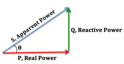
The power factor is defined as the ratio of real power to apparent power. As power is transferred along a transmission line, it does not consist purely of real power that can do work once transferred to the load, but rather consists of a combination of real and reactive power, called apparent power. The power factor describes the amount of real power transmitted along a transmission line relative to the total apparent power flowing in the line.The Power Triangle:

We can relate the various components of AC power by using the power triangle. Real power extends horizontally in the î direction as it represents a purely real component of AC power. Reactive power extends in the direction of ĵ as it represents a purely imaginary component of AC power. Complex power (and its magnitude, Apparent power) represents a combination of both real and reactive power, and therefore can be calculated by using the vector sum of these two components. We can conclude that the mathematical relationship between these components is:
![{\displaystyle {\begin{aligned}S&=P+jQ\\|S|^{2}&=P^{2}+Q^{2}\\[3pt]|S|&={\sqrt {P^{2}+Q^{2}}}\\\cos \theta {\text{, power factor}}&={\frac {P{\text{, real power}}}{|S|{\text{, apparent power}}}}\end{aligned}}}](https://wikimedia.org/api/rest_v1/media/math/render/svg/5a9d39c397886db320d3115702cea0ffc651326a)
Increasing the Power Factor:

As the power factor (i.e. cos θ) increases, the ratio of real power to apparent power (which = cos θ), increases and approaches unity (1), while the angle θ decreases and the reactive power decreases. [As cos θ → 1, its maximum possible value, θ → 0 and so Q → 0, as the load becomes less reactive and more purely resistive].
Decreasing the Power Factor:
As the power factor decreases, the ratio of real power to apparent power also decreases, as the angle θ increases and reactive power increases.
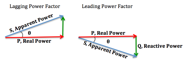
Lagging and Leading Power Factors:
In addition, there is also a difference between a lagging and leading power factor. The terms refer to whether the phase of the current is leading or lagging the phase of the voltage. A lagging power factor signifies that the load is inductive, as the load will “consume” reactive power, and therefore the reactive component is positive as reactive power travels through the circuit and is “consumed” by the inductive load. A leading power factor signifies that the load is capacitive, as the load “supplies” reactive power, and therefore the reactive component is negative as reactive power is being supplied to the circuit.
If θ is the phase angle between the current and voltage, then the power factor is equal to the cosine of the angle, :


Since the units are consistent, the power factor is by definition a dimensionless number between −1 and 1. When power factor is equal to 0, the energy flow is entirely reactive and stored energy in the load returns to the source on each cycle. When the power factor is 1, all the energy supplied by the source is consumed by the load. Power factors are usually stated as "leading" or "lagging" to show the sign of the phase angle. Capacitive loads are leading (current leads voltage), and inductive loads are lagging (current lags voltage).
If a purely resistive load is connected to a power supply, current and voltage will change polarity in step, the power factor will be unity (1), and the electrical energy flows in a single direction across the network in each cycle. Inductive loads such as transformers and motors (any type of wound coil) consume reactive power with current waveform lagging the voltage. Capacitive loads such as capacitor banks or buried cable generate reactive power with current phase leading the voltage. Both types of loads will absorb energy during part of the AC cycle, which is stored in the device's magnetic or electric field, only to return this energy back to the source during the rest of the cycle.
For example, to get 1 kW of real power, if the power factor is unity, 1 kVA of apparent power needs to be transferred (1 kW ÷ 1 = 1 kVA). At low values of power factor, more apparent power needs to be transferred to get the same real power. To get 1 kW of real power at 0.2 power factor, 5 kVA of apparent power needs to be transferred (1 kW ÷ 0.2 = 5 kVA). This apparent power must be produced and transmitted to the load in the conventional fashion, and is subject to the usual distributed losses in the production and transmission processes.
Electrical loads consuming alternating current power consume both real power and reactive power. The vector sum of real and reactive power is the apparent power. The presence of reactive power causes the real power to be less than the apparent power, and so, the electric load has a power factor of less than 1.
A negative power factor (0 to -1) can result from returning power to the source, such as in the case of a building fitted with solar panels when their power is not being fully utilised within the building and the surplus is fed back into the supply.
Power factor correction of linear loads
A high power factor is generally desirable in a power delivery system to reduce losses and improve voltage regulation at the load. It is often desirable to adjust the power factor of a system to near 1.0, such that only real power is generated or consumed. When reactive elements near the load supply or absorb that load’s reactive power demand, the apparent power demand on the generator is reduced. Power factor correction may be applied by an electric power transmission utility to improve the stability and efficiency of the network. Although not usually the case, individual electrical customers who are charged by their utility for reactive power may install correction equipment to increase their power factor so as to reduce costs.
Power factor correction brings the power factor of an AC power circuit closer to 1 by supplying or absorbing reactive power, adding capacitors or inductors that act to cancel the inductive or capacitive effects of the load, respectively. In the case of offsetting the inductive effect of motor loads, capacitors can be locally connected. These capacitors help to generate reactive power to meet the demand of the inductive loads. This will keep that reactive power from having to flow all the way from the utility generator to the load. In the electricity industry, inductors are said to consume reactive power and capacitors are said to supply it, even though reactive power is just energy moving back and forth on each AC cycle.
By cancelling some reactive power drawn by the inductive load or by reducing the reactive power supplied by the generator, there will be less energy transfer between the load and the utility generator. In turn, this helps to reduce the costs by utility boards as they do not have to generate as much power as needed. However, for the personal consumers themselves, power and monetary savings might be insignificant and this depends on how they are charged for power and the physical set up of their systems.
When households are charged for the reactive power they consume, which is generally not the case today, there will be almost no monetary incentives for them to install power factor correction equipment. This is generally the case, as household electric meters do not measure vars but only real power. Adding power factor correction tools merely affect the reactive power supplied or drawn and not real power. Thus the amount of real power drawn will remain the same and total costs of utility by the household will not be affected. However, it is possible for households to enjoy savings, albeit small, from power factor correction if there are long and high-resistance lines connecting between the utility meter and the load. In fact, using power correction tools reduces the current flowing through the lines. Hence, power loss behind the meter can be reduced by a small amount and will lead to cost savings. However, it has to be noted that this is usually insignificant for the consumers.
The reactive elements in power factor correction devices can create voltage fluctuations and harmonic noise when switched on or off. They will supply or sink reactive power regardless of whether there is a corresponding load operating nearby, increasing the system's no-load losses. In the worst case, reactive elements can interact with the system and with each other to create resonant conditions, resulting in system instability and severe overvoltage fluctuations. As such, reactive elements cannot simply be applied without engineering analysis.
An automatic power factor correction unit consists of a number of capacitors that are switched by means of contactors. These contactors are controlled by a regulator that measures power factor in an electrical network. Depending on the load and power factor of the network, the power factor controller will switch the necessary blocks of capacitors in steps to make sure the power factor stays above a selected value.
Instead of using a set of switched capacitors, an unloaded synchronous motor can supply reactive power. The reactive power drawn by the synchronous motor is a function of its field excitation. This is referred to as a synchronous condenser. It is started and connected to the electrical network. It operates at a leading power factor and puts vars onto the network as required to support a system's voltage or to maintain the system power factor at a specified level.
The synchronous condenser's installation and operation are identical to large electric motors. Its principal advantage is the ease with which the amount of correction can be adjusted; it behaves like a variable capacitor. Unlike capacitors, the amount of reactive power supplied is proportional to voltage, not the square of voltage; this improves voltage stability on large networks. Synchronous condensers are often used in connection with high-voltage direct-current transmission projects or in large industrial plants such as steel mills.
For power factor correction of high-voltage power systems or large, fluctuating industrial loads, power electronic devices such as the Static VAR compensator or STATCOM are increasingly used. These systems are able to compensate sudden changes of power factor much more rapidly than contactor-switched capacitor banks, and being solid-state require less maintenance than synchronous condensers


No comments:
Post a Comment